Captop and head position _ Printer Cleaning Issues Part 5 ARTJET 2026
So far, I have summarized the information related to UV Printers below. If you click on the article, you will be taken to the link for related information.
9 articles on head basics,
12 articles on actual head issues and their solutions,
10 actual mechanical Machine Problems and Solutions.
12 Problems and Solutions of Electronic Boards and SW Actually Issued
11 Problems and Solutions: Sai Rip Installation and Basic Settings, Spot Color Creation, and More
We’ve compiled a list of products that can be made with a UV printer.
I. Background information
We’re updating previous content.
The full text of Part 24 of the Ink Supply Issues series can be found through the link below.
24 articles on ink supply issues,
This article explains the captop and head position, which are highlighted in red in the entire table of contents for ink supply issues.
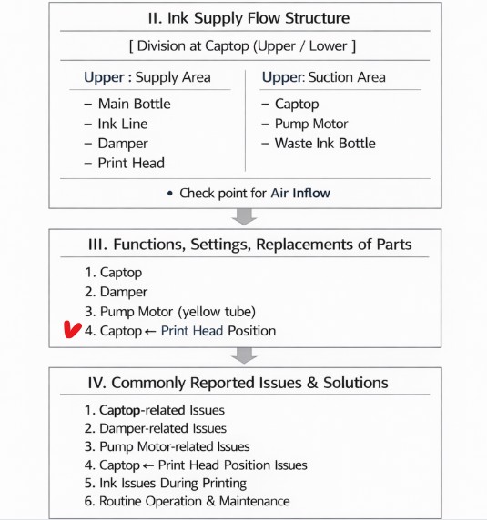

When ink flows from the main ink bottle through the ink tube to the damper, it flows through the print head to the captop, then through the motor pump to the waste ink tank.
- The first session covered the captop lower tube,
- The second session covered how to replace the captop,
- The third session covered the damper.
- In the fourth hour, I explained about the pump motor and the yellow tube.
You can find more information by clicking the relevant link.

Pump motorToday, I will explain the Captop and head positions that you should check when pumping does not occur even after checking each part explained above.
II. Equipment inspection items
1. Capping station horizontality
The head and capping station are items to check during initial equipment setup.
If the head base and captop are not positioned correctly, cleaning or pumping will not occur properly.
Below is a photo of the X-axis home position checked without the head mounted.
I will explain the head and captop positions later, but first, I will explain the leveling of the capping station, which should be checked.
This issue can also occur if the head carriage base plate, where the head is mounted, is tilted. However, as this is rare, it will not be explained here.
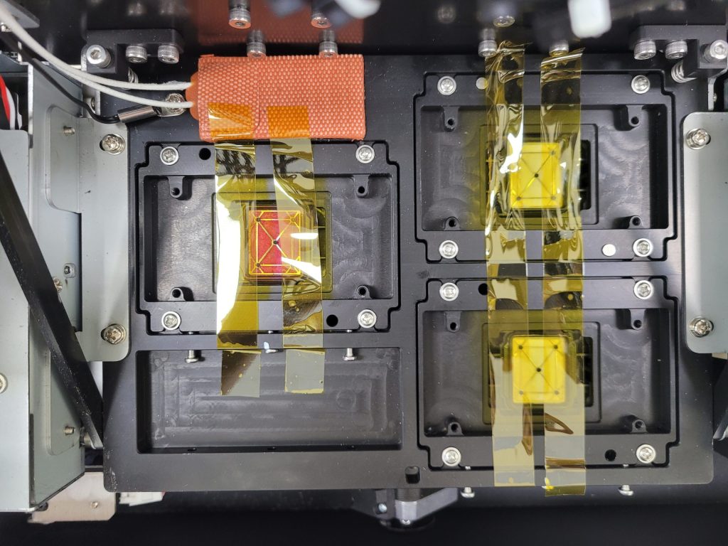
Leveling the Capping Station
- Before installing the head, check the level of the entire assembly (called the capping station) and the entire plate.
- If the capping station plate is tilted too far to one side, even if the captop and head are aligned, pumping may not occur for a specific head.
- For example, while the color head may pump well, the white head, which is tilted too far, may not seal properly on one side, resulting in poor pumping.
- Conversely, white may pump well, but color may not.
- Even if there is a spring at the bottom of the captop, if the carriage base plate is tilted too far to one side,
- one side will receive more force, while the other side will receive less force, resulting in poor sealing on the less forceful side. This can cause problems.
“Really? Do I really need to level everything? The captop is attached to the bottom of the head by a spring…”
I’m sharing the symptoms of an actual problem I encountered due to a leveling issue with the capping station.
- The nozzles on White channels 1 and 2 recovered immediately after cleaning, but channels 3, 4, 5, and 6 didn’t recover properly.
- Replacing the captop immediately resolved the issue, but the next day, the same problem occurred.(Captop blade is good, then shot time it works)
- It wasn’t that the ink load (pumping) wasn’t working.
- The capping station was tilted. While ink flowed smoothly in White channels 1 and 2,
- the ink flowed poorly in White channels 3, 4, 5, and 6, which were at an ambiguous angle, didn’t flow properly during ink loading (pumping), preventing nozzle recovery.
For over a month, the White nozzle was in good and bad shape, and I tried various adjustments without success. Finally, leveling the capping station resolved the issue.
I struggled to resolve the issue, so I’m sharing this with you.
III. Aligning the Captop and Head Position
You need to adjust all three settings: left/right, front/back, and height.
1. Adjust left and right along the X-axis
The X-axis home position is the position where the head is capped against the captop when the printer is not in use, and also the position during cleaning or pumping.
If this home position is not aligned correctly with the captop,
- the vacuum will be broken when the printer is not in use, preventing proper head protection.
- During cleaning, ink will not flow to the waste ink tank, preventing proper cleaning.
- During pumping, the seal will not be properly sealed, preventing proper pumping.
While the software varies depending on the printer, there is a software function that sets the X-axis home position.
This explanation is based on the printers we sell.

Let’s set the left/right position of the head carriage X-axis home position. Let’s move it 1mm further to the left, toward the platen.
- Click [Bi-Direction] in the software.
- Adjust the [Origin springback (mm)] value. Although it’s displayed in [mm], it’s not in mm. Adding or subtracting 3 moves it by approximately 1mm.
- If we add 3 to the current value of 87, making it 90, we’ll move it 1mm further to the left, changing the X-axis home position.
- Enter 90 instead of 87 and click the [Save] button.
- Exit the software and click the [Reset] button at the top of the software. This will move the entire head carriage 1mm to the left (toward the platen), changing the home position.
The X-axis left/right direction can be adjusted using the software program.
2. Adjust the Y-axis forward and backward direction
The X-axis can be adjusted left and right with software, but the Y-axis cannot be adjusted forward and backward.
You need to loosen the bolts securing the capping station and manually adjust the position.
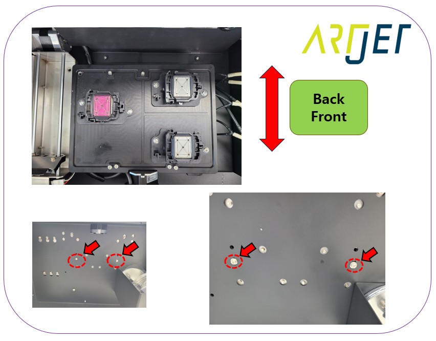
- There are two bolts holding the entire capping station block together.
- Looking above the waste ink tank, you can see two bolts, as shown in the photo below. Loosening them creates a small amount of play that allows the capping station to move forward and backward.
- With the software pumping (inkload) running, manually move the capping station slightly until you reach a point where ink flows into the waste ink tank.
- Refasten the bolts at that point and check the pumping again. While the ink may pump, it may not flow during cleaning. Therefore, repeat the process to adjust the front and back positions.
- Since the entire plate position has been changed, you need to check that the other colors are pumping properly as well.
- Although the positioning error is not that much, this task may take more time than expected because the three heads for color, white, and varnish must be aligned exactly.
3. Height of capping station
If the head and captop are aligned correctly left-right and front-to-back, the next step is to:
check the height at which the captop rises to seal the head.
- Average height of 5 is generally used.
- If the height is too low, such as 3 or 4, the captop and head may not seal properly, preventing pumping.
- If the height is set too high, such as 6 or 7, the head may touch the captop cloth, causing ink in the damper to leak onto the cloth, causing printing problems.

To adjust the capping station height, go to:
- [Menu] => [Printhead Cleaning Setting or similar name] => Elevator Mechanism (mm) => Capping Height 4
- To change the number, double-click the number 4. This will activate the corresponding window.
- Enter the number you want to change and click the [OK] button in the lower left corner.
- To close the window, click the x button in the upper right corner.
I’m sharing a problem I had a hard time with because the capping station height was set too high.
“No way… the ink load (pumping) is working fine, and printing is fine. Are you just trying to scare me?”
- This was a problem that I struggled with for a month, unable to find the cause.
- Two weeks after delivery, the LC or LM suddenly started to fall out during printing.
I checked everything from the ink tube, and without finding the cause, I even replaced the entire ink line. However, the same problem occurred two days after replacing the ink line. - Just in case, I replaced the cap top, and suddenly, all the problems were solved.
- I thought it was fixed, but a week later, the same problem occurred.
- I checked everything and found nothing wrong, and with no other option, I replaced the cap top again. And it was fixed again.
- After a week of no problems, I thought it was just a lucky fix.
- But 10 days later, the same problem occurred again.
The problem was caused by the capping station height being set too high.
- When the captop was first replaced, the rubber blade was still intact, preventing the print head nozzle from contacting the captop’s inner fabric.
- Over time, the rubber blade weakened, causing the bottom of the print head to contact the captop’s inner fabric, causing ink to continuously leak from the damper.
- Because the height setting was inaccurate, sometimes the print head would contact the captop’s inner fabric, draining all the ink in the damper. This caused ink to run out during printing, leading to a problem.
- Other times, the print head wouldn’t contact the fabric, preventing ink from flowing out.
- Ultimately, changing the capping station height from 6 to 5 resolved the issue without any parts replacement.
- As such, capping station height setting is a crucial factor.
IV. Problems arising from captop and head position
1. “Ink and bubbles come out together.”
Ink comes out of the waste ink tank, but sometimes it’s mixed with a lot of bubbles.
This happens when the bottom of the print head and the captop don’t align perfectly, and air gets trapped in the corners.
In this case, pour white ink into the captop, move it to the left while the print head is capped, and without cleaning the print head, look at the bottom of the head to see the captop’s position.
You can adjust the captop’s position based on the ink marks on the print head surface.

When making even minor adjustments, it’s best to adjust the captop position by loosening the two bolts shown in the image below, rather than moving the entire capping station.
However, if there’s no room to move, you’ll have no choice but to move the entire capping station.

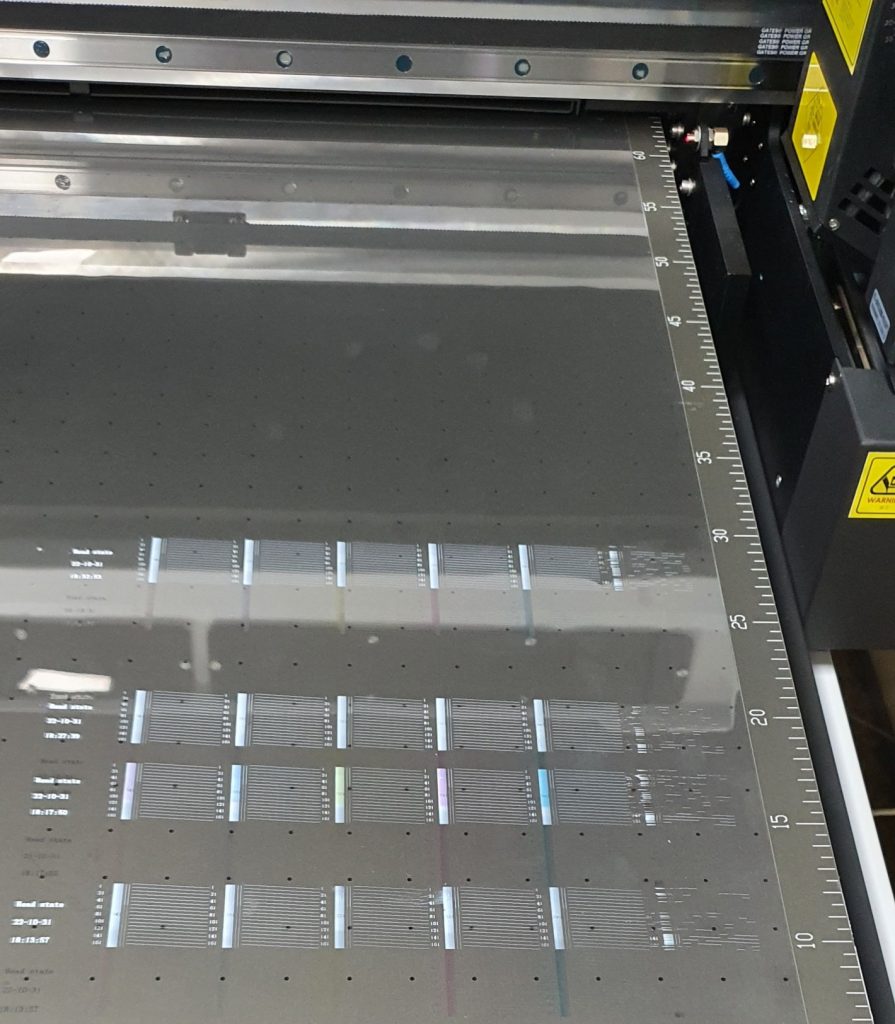
2.”Pumping works fine, but the end channel just doesn’t come out.”
The captop rubber blade is pressing against the end channel nozzle.
It’s pressed against the head surface, creating a seal and allowing ink to load (pump) properly.
However, the captop rubber is blocking the nozzle heat in the end channel, preventing ink from flowing out.
This issue also occurs only in one channel, although pumping and cleaning are working fine. It took a while to figure out the cause.
This issue has occurred twice so far. If only one channel is not flowing out, this should be considered.
In addition
If ink loading (pumping) fails, cleaning will fail and printing will be impossible, so ink loading (pumping) must be resolved.
Ink loading (pumping) problems can be caused by a variety of factors, including the captop, damper, motor pump, and the position of the print head and captop.
From now on, I will discuss actual problems and solutions, as well as provide more detailed information.
V. ARTJET UV Printer
One thing I’ve noticed after five years of sales and maintenance of ARTJET UV printers is that troubleshooting data is second only to product stability.
All products have issues, whether they’re caused by actual equipment problems or consumer error. Product stability hinges on how quickly and easily you can resolve those issues.
ARTJET compiles all troubleshooting data.
You can see the product print quality by clicking here.
Click here for ARTJET pricing and terms of sale. The exterior design has changed.

핑백: Aligning the Captop and Head Position - Printer Cleaning Issues Part 6 ARTJET 2026
핑백: When the capping station level is not correct - Printer Cleaning Issues Part 7 ARTJET 2026
핑백: How to Replace a Motor Pump Tube - Printer Cleaning Issues Part 12
핑백: Why it's important to replace the yellow tube and captop - Printer Cleaning Issues Part 14 ARTJET 2026
핑백: Head protection plate crumpled _ Printer Cleaning Issues Part 15 ARTJET 2026
핑백: Head protection plate cracked _ Printer Cleaning Issues Part 16 ARTJET 2026
핑백: When ink runs out during printing - Printer Cleaning Issues Part 17 ARTJET 2026
핑백: The color has faded - Printer Cleaning Issues Part 18 ARTJET 2026
핑백: White flies around the image - Printer Cleaning Issues Part 19 ARTJET 2026
핑백: When to replace the damper - Printer Cleaning Issues Part 20 ARTJET 2026
핑백: Problems that occur when ignoring the low ink alarm - Printer Cleaning Issues Part 22 ARTJET 2026
핑백: White cleaning methods that might clogged - Printer Cleaning Issues Part 23 ARTJET 2026