
- Operators and technicians who run and maintain UV printers
- Anyone replacing a printhead who is concerned about power-off steps and flat cable contamination
- Users who have experienced wrong colors due to an incorrect damper order
- This guide is based on real field experience — the same symptom can have different root causes
- Disconnecting / reconnecting DATA cables while power is ON can burn the cable and damage the head / board
- With White / Varnish lines, ink may drip during removal — protect the flat cable with tissue before you start
- Never loosen the large mounting bolts around the head — they are a mechanical alignment jig, not a serviceable part
- To avoid accidents during printhead replacement, follow this sequence: (1) Release capping → (2) Power OFF everything → (3) Record damper order → (4) Protect DATA/flat cable from ink
- Ink contamination inside the DATA cable connector is nearly impossible to recover from — protect the area before any ink can drip
- If dampers are reconnected in the wrong order, the colors the software sends and the ink that actually jets will be swapped, producing completely wrong colors
- After installing the new head, confirm carriage position, power-on sequence, and whether the board LEDs blink abnormally before printing
- Ink supply issues (including cleaning/pumping) were recently updated.
- If your printer uses dampers, many cases can be solved via the link below.
- This is a 23-post index with photos.
- ARTJET 2026: Cleaning Troubleshooting (23 Posts)
- Part 1: Symptoms & Fix When a DATA Cable Is Contaminated by Ink
- Part 2: 17 Stored Used Heads: How Many Worked After Alcohol Cleaning & What Errors Appeared
- Part 3: A Specific Color Prints Abnormally During Printing
- Part 4: How to Handle Reflective Materials + a More Dangerous Cause That Can Clog Nozzles
- Part 5: Real Case: Reviving a White Head Not Used for One Month
- Part 6: Symptoms When a Printhead Reaches End-of-Life and How to Swap Heads
- Part 7: Why Banding Appears Only on Certain Solid Colors + Tips to Reduce It
- Part 8: A Case Where a Color Still Didn’t Print Even After Replacing the Head
- Part 9: Print Motion but No Ink Output
- Part 10: Symptoms of a Cracked Ink Channel Inside a Print Head
I. Before Printhead Replacement — Printhead Replacement Video and Precautions
When the printer is in the capping position, the cap top is tightly sealed against the printhead. You can remove the head in this state, but during installation the cap top is raised, which forces you to push it down while tightening bolts.
To avoid this, exit the capping position before starting the replacement.
- In ARTJET software, press the left arrow button to release the capping state.
- Once released, the head carriage will move to the left.
- After moving about 20 cm, press the left arrow button once again.
- The carriage will stop at that position.
Some users try to move the carriage using the left arrow on the front touch panel.
On the ARTJET touch panel, you must keep holding the left arrow button to release capping.
That’s why using the left arrow in ARTJET software is usually more convenient.
When installing a new head, you may need to disconnect and reconnect the DATA cable. If you do this while power is ON, the DATA cable can burn and the head/board can be damaged.
Therefore, you must turn OFF all power before replacing the head.
In one real case, a customer forgot to power OFF the machine during replacement and the DATA cable was burned. Fortunately, the head and the main board were not damaged in that case.
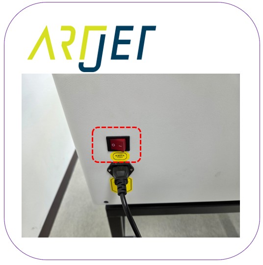
Before you start, make sure all power is OFF. Follow this shutdown order:
- With the head carriage positioned to the left, close ARTJET software.
- On the touch panel: Power button OFF, Lamp button OFF, Suction button OFF.
- Main switch OFF (left rear side).
- Main switch OFF (rear side). After this, all power is cut and you can move the flatbed and head carriage by hand.
- Move the head carriage to a position that is convenient for work.
II. Removing the Used Printhead — Printhead Replacement Video and Precautions
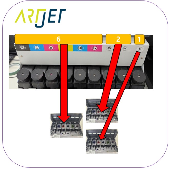
Before removing dampers for a color head replacement, take a photo of the damper color order. When installing the new head, reconnect the dampers in the exact same order.
- If the damper order is mixed up after head replacement, correct color output will not be possible
- For example, if you connect a Magenta damper to the Cyan position, the software sends Cyan data but Magenta ink will jet from the Cyan channel
- If the dampers are connected incorrectly, colors will be completely wrong
When you remove a damper from the head, ink may drip from the connection.
For color channels (1:1 connection), ink usually does not flow heavily after removal. However, for White and Varnish (shared ink supply structure), ink may flow out at the moment of removal.
⚠️ The Most Dangerous Point During Ink Drips
If dripping ink falls onto the DATA/flat cable, it can travel down the cable into the connector area and damage both the DATA cable and the printhead. Once ink penetrates the connector area, it is nearly impossible to recover even with alcohol cleaning.
Place tissue/paper under the marked area so any drips do not touch the cable. If ink drops, replace the tissue immediately to keep ink away from the cable.
After removing dampers, prepare two paper cups and place about three dampers in each cup. Ink can continue to leak from removed dampers, so this prevents spreading.

Do NOT loosen the large bolts you see around the head.
Those bolts belong to the mechanical mounting block used to keep head alignment (vertical/height) accurate. If you remove them, you may need to re-check mechanical alignment and redo software offsets — this takes significant time.
After removing the dampers, you will see four bolts at each end inside the head area. Remove only those bolts to detach the head. If the head is stuck due to ink residue, use a flat-head screwdriver to carefully separate it. Keep the bolts safe — you must reuse them.
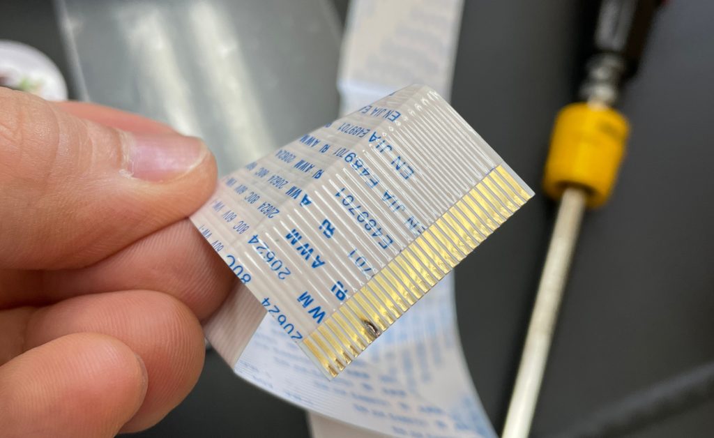
When disconnecting the DATA cable, support the front of the cable with your fingers and pull it out horizontally to avoid damage. Also prevent the gold contacts from being contaminated by ink or debris.
III. Installing the New Printhead — Printhead Replacement Video and Precautions
The left/right DATA cable must be connected to the new head in the exact same orientation as the old head. If the cable sides are swapped, ink jetting will not work.
After connecting the cable, insert the bolts and tighten them after confirming the exact positions. Tighten in a diagonal cross pattern. Do not fully tighten one bolt at once — tighten gradually and evenly.
Reconnect dampers in the exact same order as the photo you took before removal. Prevent ink from dripping onto the DATA/flat cable during reconnection. If dampers are not fully seated, pumping/cleaning issues can occur — press firmly to confirm proper seating.
In the image below, refer to the [Damper + print head] section.

If the head carriage is positioned at the far ends of the X-axis, initialization may fail because the carriage may pass the X-axis limit sensor.
Before turning on the main switch, move the head carriage about 20 cm to the left from the capping station. Then: Main power switch ON → Touch panel power button ON → Check if the board LEDs are blinking abnormally.
If you see blinking LEDs, power OFF immediately and re-check the DATA cable connection.
The replaced head has no ink inside, and ink may have drained from the dampers when removed, so dampers may not be fully filled either. Run pumping so ink flows into the dampers and the head.
After pumping, if ink flows to the waste ink tank for about 5–10 seconds without bubbles, stop pumping. Then run cleaning and check nozzle status using the Test button.
If nozzles are missing during image printing, repeat: Ink load (pumping) → cleaning → nozzle test → test image printing, until head condition stabilizes.
V. ARTJET UV Printer
