
- Users experiencing blurry small text or color bleeding during printing
- Users whose print colors don’t match the intended color tone
- Users who want to precisely calibrate offset values after a head replacement or initial setup
- Users who want to systematically align Color / White / Varnish channels from scratch
- After adjusting the offset, always press the Save button to apply changes. Closing without saving will reset all values.
- White vertical values have opposite sign direction compared to the Color head. Adjusting based on absolute numbers alone will apply the opposite direction — always verify before proceeding.
- Bidirectional offset must be set last, only after completing all three steps: Positive / Reverse / Vertical. Skipping this order will prevent accurate bidirectional alignment.
- Aged print heads may lose ink trajectory accuracy, causing bidirectional offset drift. Regular inspection is recommended.
- Offset adjustment order: Color → White (per channel) → Varnish, each with Left→Right / Right→Left / Vertical / Bidirectional sequence
- All channels are aligned to Black (K) as the reference — K values are never changed
- White has 6 identical channels, so lock 5 channels and tune 1 at a time for precision
- Using actual print images instead of built-in software offset images yields more accurate results
I. Offset Adjustment Order — Head offset precision tuning
In most cases, the mechanical alignment (head vertical direction) is already correct, so we will proceed directly to Offset adjustment.We will first cover the overall sequence, then provide detailed instructions for adjusting the offset of each head.
If the offset is not accurately set:
- Small text may not print sharply, and colors may shift to an incorrect tone due to offset deviation.
- To achieve sharp detail and accurate color reproduction, head pin values must be precisely calibrated.
1. Offset Adjustment Windows in the Software
Our software includes 4 offset adjustment windows, offering more precise control compared to other UV printers on the market.
The 4 windows are described in order as follows:
1. Window for aligning Color, White, and Varnish channels when printing Left → Right
2. Window for aligning Color, White, and Varnish channels when printing Right → Left
3. Window for aligning Color, White, and Varnish channels that deviate in the vertical direction during printing (This function is not available on other printers — it is a unique advantage of our machine)
4. Window for aligning all channels during bidirectional printing.
As was the case with high-end large-format UV printers,
using actual print images for channel offset alignment is more accurate than using the built-in offset images in the software.
For this reason, we use actual print images — not the software’s built-in offset images — to perform offset alignment.
2. Offset Flowchart and Images Used at Each Step
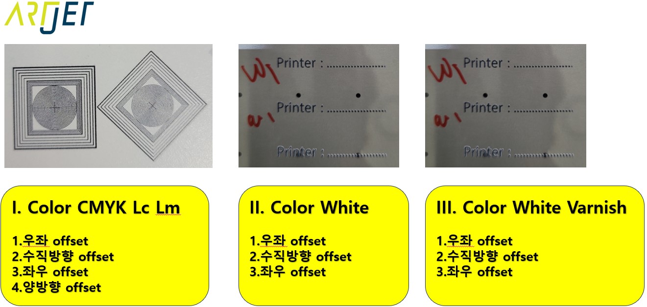
For Color, White, and Varnish — all offset alignment is based on Black (K) as the reference.
1. Color Head Offset Alignment
- When printing Right → Left, adjust the offset using the circle image so that C, M, Y, Lc, and Lm align in a straight line relative to Black (K).
- Then, when printing Left → Right, repeat the same process to align C, M, Y, Lc, and Lm to Black (K).
- After completing both Right → Left and Left → Right offsets, adjust the vertical offset so that C, M, Y, Lc, and Lm form a straight line relative to K.
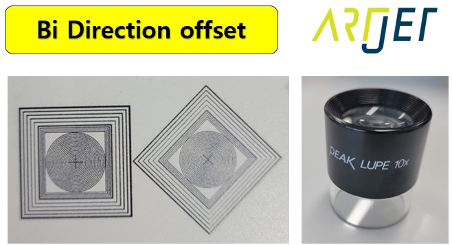
- Once all three are done, align the overall bidirectional offset.
2. White Head Offset Alignment
- Follow the same process as the Color head: align Right → Left, Left → Right, and Vertical — three adjustments in total.
- Bidirectional offset shares the same value across Color, White, and Varnish, so it follows the Color head. No separate adjustment is needed.
- Note that White consists of 6 channels, each of which must be aligned individually. This will be explained in detail later.
3. Varnish Head Offset is performed using the same method as White.
II. Color Head Pin Value Offset — Head offset precision tuning
1. Overview of the Offset Window
In the image below, clicking the No.1 color icon brings up the Offset window shown in the second image.

Here is a detailed explanation of this window:
- Looking at No.3 and No.4, you will see numbered entries from 1-2 to 1-18, all of which are active.
- 1-1 represents Black, which is the reference for all channels — it has no editable number and the button is not active.
- 1-2 through 1-6 correspond in order to: C, M, Y, Lc, Lm.
- 1-7 through 1-12 are W W W W W W — the 6 White channels. In the software channel view, these may appear as W1,W1,W1,W1,W1,W1 or as Spot 1: S1,S1,S1,S1,S1,S1.
- 1-13 through 1-18 are V V V V V V — the 6 Varnish channels. In older software versions, these appear as W2,W2,W2,W2,W2,W2 (originally should be V1 — do not be confused). In updated software, they are labeled as Spot 2: S2,S2,S2,S2,S2,S2.
2. Color Head Pin Value — Left→Right and Right→Left Offset
1. Image and Materials
- The image to be used is shown below.
- Printing on a White background allows accurate offset alignment when Color and White are printed simultaneously.
- From the ARTJET QC image provided at delivery, crop only the section below in RIP, and set Spot 1 to the [Media] option to create the Ripping file.
- Prepare this image along with a 10x loupe magnifier if available (helpful but not required).
2. Left → Right Pin Value Offset Adjustment
In the offset adjustment window, No.2 and No.4 are linked.
- Positive refers to printing from Right to Left (upper green arrow direction), displayed as “Single leave” in the software.
- Reverse refers to printing from Left to Right (lower green arrow direction), displayed as “Single return” in the software.
- Regardless of Positive or Reverse, entering “+” in No.4 moves the selected channel to the Left, and “-” moves it to the Right.
Using Magenta as an example, here is how to perform the Left → Right pin value offset adjustment.
- Select Positive — printing from Right to Left (upper green arrow direction), shown as Single leave in the software.
- Exit the offset adjustment window and print the circle image shown above.
- When viewed through a magnifier, assume the printed result looks like the left image below. (For clarity, only Black and Magenta are shown — other colors are omitted.)

- The left-right value adjustment window is No.4.
- Magenta is shifted to the right relative to Black in the horizontal direction. (Vertical deviation is ignored during this step.)
- Since Black is the reference channel and cannot be moved, Magenta must be shifted toward Black — i.e., to the left.
- In the No.4 adjustment window, Magenta corresponds to 1-3, and its current value is [124].
- To move Magenta to the left, add +1 to 124 to make it 125.
- After making changes, you must click the “Save” button at the bottom right of the adjustment window to apply them.
- After clicking “Save” and then “Close”, print the same image again from the print window.
- The result should now look like the right image — Magenta aligned horizontally with Black.
- If not aligned in one attempt, repeat the process until the best possible value is reached.
- Horizontal offset moves in increments of 1 unit, adjusted using the up/down arrows.
Once Magenta is complete, perform the same Left → Right pin value offset (Positive, Single leave) for Cyan, Yellow, Lm, and Lc.
3. Right → Left Pin Value Offset Adjustment
Selecting Reverse in No.2 of the offset adjustment window will automatically switch No.4 to the Right → Left section.
- As noted above, Reverse refers to printing from Left to Right (lower green arrow direction), displayed as “Single return” in the software.
- Regardless of Positive or Reverse, entering “+” in No.4 moves the channel to the Left, and “-” moves it to the Right.
The adjustment method is identical to the Left → Right pin value offset described above.
3. Color Head Pin Value — Vertical Offset Adjustment
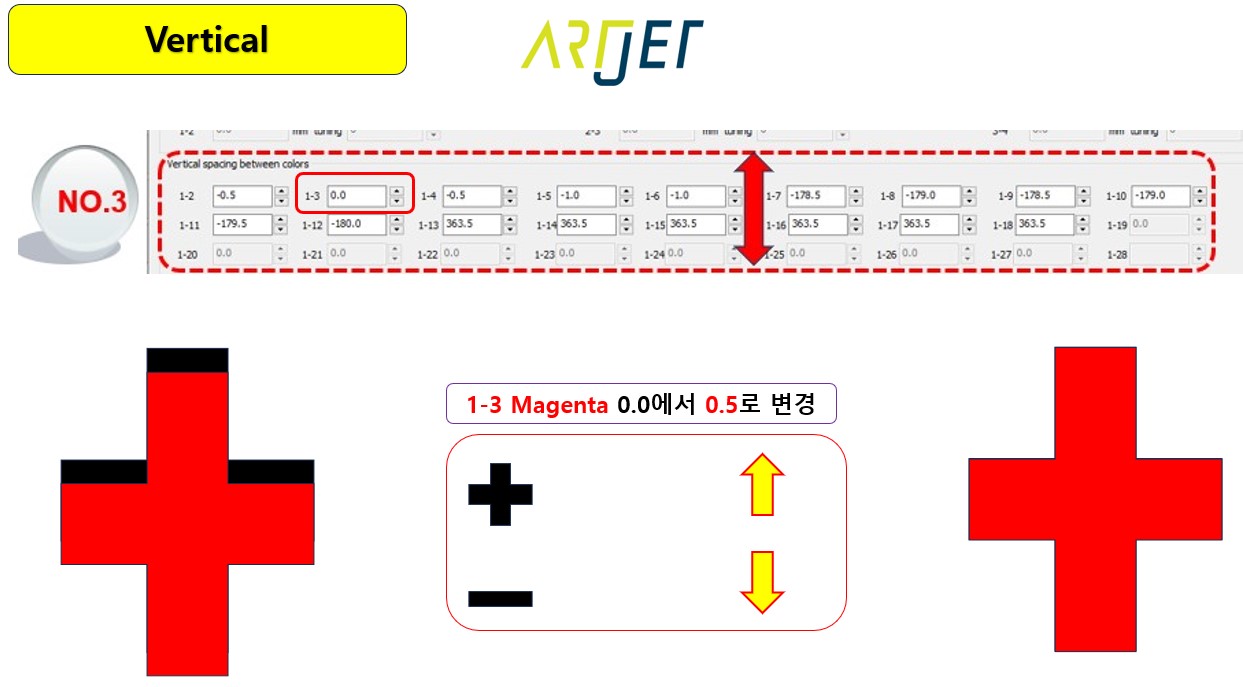
Offset adjustment window No.3 is used to adjust offset in the vertical direction — not left or right.
- Magenta is sitting below Black, so it needs to be moved upward.
- Magenta corresponds to 1-3 in No.3, and its current value is 0.0.
- For the Color head, increasing the value moves the channel up; decreasing moves it down.
- To move Magenta up to match Black, add +0.5 to 0.0 to set it to 0.5.
- Vertical offset moves in increments of 1 unit when using the arrow buttons.
- For 0.5-unit adjustments, you must manually type 0.5 using the keyboard.
- After making changes, click the “Save” button at the bottom right to apply.
- After “Save”, click “Close” to exit the window and print the image.
- Repeat this process until the optimal value is found.
4. Color Head — Bidirectional Offset Adjustment
Once the Left→Right, Right→Left, and Vertical offsets for the Color head (CMYKLcLm) are all complete, proceed to the Bidirectional Offset adjustment.
All three adjustments must be completed before the bidirectional offset is set — otherwise the bidirectional value cannot be accurately established.

To reiterate: the Positive (Right → Left) and Reverse (Left → Right) offsets must both be accurately set before bidirectional offset can be correctly aligned.
- Bidirectional offset can be adjusted and saved per scan speed setting.
- Our print mode uses Scan speed: Normal and Feed speed: Normal — bidirectional alignment is based on these settings.
- In the rightmost section of the window, use the up/down arrows next to Value 12 to adjust in increments of 1.
- Clicking the “1/2*” arrow button allows adjustment in 0.5-unit increments.
- Since the direction (left or right) is not indicated, the optimal value must be found through trial and error using “+” and “-“.
- After making changes, click the “Save” button at the bottom to apply.
- Bidirectional focus may vary depending on head height. Since the flatbed surface may not be perfectly level across the entire area, some zones may be sharp while others appear out of focus.
- Aged heads may also lose ink trajectory accuracy, causing bidirectional offset drift.
- This value should be checked and adjusted periodically.
III. White Head Pin Value Offset — Detailed Instructions
1. White Has 6 Channels
The Color head has individually distinct channels: C, M, Y, K, Lc, and Lm.
However, all 6 White channels are identical in color.
- If all White channels are active during offset adjustment, it is impossible to identify which specific channel is misaligned.
- While a general alignment is possible, precision tuning requires locking 5 of the 6 channels and adjusting one at a time.
- The procedure is identical to Color Offset adjustment — the only difference is the channel locking step.
- Black can be used as the reference, or since CMYK Lc Lm offset has already been completed, the Color head can simply serve as the reference.
- Once Positive, Reverse, and Vertical are aligned for each White channel, bidirectional offset does not need to be set separately.
- Bidirectional alignment will naturally follow the values set during the Color head adjustment.
2. Locking White Channels and Adjusting One at a Time
1. How to Lock White Channels

In the leftmost image above, clicking the box inside the dotted area opens the center window shown in the middle image.
In the center window, channels 7 through 12 are the White channels.
Leave channel 7 active and click the down arrow on the right side of channels 8 through 12, selecting “Close” for each.
After completing all changes, click “Save” then “Close”. As shown in the third image:
- What was previously W1,W1,W1,W1,W1,W1 (or S1,S1,S1,S1,S1,S1)
- will now change to W1,off,off,off,off,off — with only the first White channel active and printing.
2. White Offset Adjustment Procedure
Image notes:
- The image below is cropped from the text portion of the ARTJET QC image.
- White Spot Color option is set to “solid color mode” — White is printed only where color is present.
Print the image below and set Positive, Reverse, and Vertical offset for White channel 1 using the same method as the Color head.
Note: For White vertical values, the sign is negative. To move upward, you increase the value — but because the starting value is negative, the absolute number decreases.
In other words, adjusting based on absolute numbers alone — as with the Color head — will apply the correction in the opposite direction. Always proceed with caution.

Once channel 1 is complete, activate only the second channel and repeat the same process:
- off,W1,off,off,off,off,
- Continue in sequence for each channel.
- off,off,W1,off,off,off,
- off,off,off,W1,off,off,
- off,off,off,off,W1,off,
- off,off,off,off,off,W1,
- Once all 6 White channels are complete, set all channels back to On.
- W1,W1,W1,W1,W1,W1,
IV. Varnish Head Pin Value Offset — Detailed Instructions
The procedure is the same as White.
However, Varnish has the following characteristics:
- Varnish is jetted and then cured by the LED lamp after several additional passes — making it harder to align as precisely as White.
- Varnish ink has a natural cohesion after being ejected, meaning it tends to land in approximately the correct position even without perfect alignment.
Given these characteristics, it is acceptable to adjust only the first Varnish channel for Positive, Reverse, and Vertical offset — then apply those same values to Varnish channels 2 through 6.
If you require more precise tuning, you may proceed channel by channel using the same method as White.
V. ARTJET UV Printer
